Tampilkan postingan dengan label whatis. Tampilkan semua postingan

Minggu, 08 Juli 2012

How to calibrate Displacer level transmitter

Calibration procedure - Displacer type level transmitter

displacer_type_level_transmitter_calibration_installation_commissioning


Procedure:

*Ask panel man to put the controller in manual mode for control loop and to put it on MOS for ESD loop.
*Hook up HART Communicator and verify some parameters by refer to data sheet. Typical parameters are, tag number, PV, LRV and URV.
*Isolate the instrument from the process.
WARNING – If the process is hazardous, please unsure proper flushing is done to remove the entire hazard.
Remove isolation drain valve and open the vent flange
*Connect water pump to drain line and line up the reference tube
*Calculate the new measurement to get equivalent up trust force with S.G and length
*Mark on the chamber for reference calibration
*Hook up a multimeter in series with the signal to the DCS to measure current signal.
*Apply water level until 0% marking on chamber
*Multimeter should show 4mA
If not, do zero adjustment at transmitter using HART Communicator
Apply water level until 100% marking on chamber
*Multimeter should show 20mA
*If not, do span adjustment at transmitter using HART Communicator
*Verify the linearity by increasing and decreasing the pressure (0%,25%,50%,75%,100%,75%,50%,25% and 0%of range)
*After completion of the job ask panel operator to put loops back in normal mode or normalize the MOS


Example Calculation:
Low S.G=0.802
High S.G= 0.992
A= 810mm (measurement length)
0%    = (A x Low S.G)
    = (810 x 0.802)
    = 649.42 mm
100%     = (A x High S.G)
    = (810 x 0.992)
    = 803.52 mm

Related posts:
DP type level transmiiter
DP type level - Capillary
Bubbler type level transmitter

Sabtu, 07 Juli 2012

How to calibrate differential pressure level transmitter bubbler type?
How to calibrate Dp level bubbler type


differential_pressure_level_transmitter_bubbler_type_calibration_installation


Calibration procedure:

*Ask panel man to put the controller in manual mode for control loop and to put it on MOS for ESD loop.
*Hook up HART Communicator and verify some parameters by refer to data sheet. Typical parameters are, tag number, PV, LRV and URV.
*Isolate the instrument from the process and the purge system.
WARNING – If the process is hazardous, please unsure proper flushing is done to remove the entire hazard.
Remove the tubing connection at manifold to the process after released the process pressure
*Connect pressure calibrator to high side of the manifold
*Expose the low side to atmosphere
*Hook up a multimeter in series with the signal to the DCS to measure current signal.
*Apply pressure as per data sheet LRV
Multimeter should show 4mA
If not, do zero adjustment at transmitter using HART Communicator
*Apply pressure as per data sheet URV
Multimeter should show 20mA
If not, do span adjustment at transmitter using HART Communicator
*Verify the linearity by increasing and decreasing the pressure (0%,25%,50%,75%,100%,75%,50%,25% and 0%of range)
*After completion of the job ask panel operator to put loops back in normal mode or normalize the MOS


Example calculation

 S.G=0.89
A= 2000mm (measurement length)
B = 100mm (off set)
Dp = pressure at high side – pressure at low side
LRV    = ( B x S. G) – pressure at low side
    = (100mm x 0.89) – 0
    = 89 mmH2O
URV     = ((A+B) x S.G) – pressure at low side
    = (2100mm x 0.89) – 0
    = 1869 mmH2O


Related posts:
Differential pressure level transmiiter
Differential pressure flow transmitter
Flow transmitter pitot tube
Control valve calibration

Sabtu, 24 Desember 2011

Ingression protection

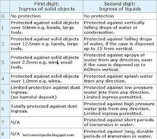
While reading the instrument specification or electrical equipment specification you might have seen IP classes.IP is interpreted as Ingress protection.Ip calsses stands for specifying the environmental protection of electrical equipments. With ingression protection class we can understand, an instrument can withstand in which environmental condition. While selecting the instrument it is important to consider the ip class. Price of the instrument also varies according to their ip class.

IP class is represented with number. First digit of IP indicates how much the instrument is protected from dust. Second digit of the IP rating indicates how much the instrument is protected from water.

First digit of IP rating
0 = No protection
1 = Protected against touch by hands (>50mm)
2 = Protected against touch by fingers (>12mm)
3 = Protected against tools and wires (>2.5mm)
4 = Protected against tools and small wires (>1mm)
5 = Limited dust ingress protection
6 = Total dust ingress protection

Second digit of IP rating
0 = No protection
1 = Protected against condensation
2 = Protected against water spray < 15 degrees from vertical
3 = Protected against water spray < 60 degrees from vertical
4 = Protected against water spray from any direction
5 = Protected against low pressure water jets from any direction
6 = Protected against high pressure water jets from any direction
7 = Protected against immersion between 15cm and 1m depth
8 = Protected against long term immersion to a specified pressure

IP rating of electrical equipment or instrument


Rabu, 14 September 2011

[Tool] Unit conversion tool for Instrumentation engineer.

As an instrumentation engineer we have to do a lot of unit conversion. I got a very effective tool converting units. It is a not a software. It is an excel sheet. No need to install it but Microsoft office software must be installed in your computer for opening the tool.

You can convert the following units.

*Length
*Volume
*Molar power rate
*Volumetric flow rate
*Pressure
*Power
*Energy
*Mass
*Density
*Area
*Dynamic viscosity
*Kinematics viscosity
*Mass flow rate
*Heat transfer coefficient
*Thermal conductivity
*Heat flux
*Specific energy
*Specific Heat

Unit_conversion_tool


Download the Unit conversion tool.

I got the tool from Internet. If you are having such tools, share it..

Senin, 05 September 2011

[Update] Deatailed explanation of "How to read a Piping and Instrument Diagram(P&ID)?"

This topic is already(Piping and instrumentation diagram) discussed in instrumentpedia. But now I feel that more explanation is required on this topic.That is why I decided to write a detail post about it.
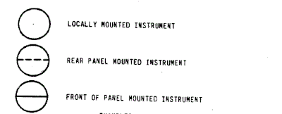
For reading a piping and instrumentation diagram someone should be very much familiar with the symbols.We can classify the instruments in to three large families.
1.Locally mounted instruments.
2.Instrument present in the front end.
3.Instrument present in the back end(Not accessible by operator. This class of instrument is located in the controller.

classification_of_instruments_in_piping_and_instrument_diagram

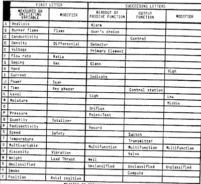
Each instrument is also identified by means of letters that describes its function as well as progressive numbers to ensure proper identification.

The first letter stands for the variable being measured.

T-Temperature
L-Level
P-Pressure
F-Flow
K-Time
S-Speed

Instrument function is represented by the second letter

I-Indicator
T-Transmiiter
R-Recorder
C-Control
D-Differential
S-Switch
E-Element
A-Alarm

Alarm function is represented by the third letter.

H-High
L-Low

Shutdown function is represented by the third and fourth letter.

H-Shut down due to a high value
L-Shut down due to a low value
HH-Shut down due to a high high value
LL- Shut down due to a low low value.

Letters used in Piping and instrumentation diagram

piping_and_instrumentation_digram_identification_letter_meaning

Some examples of instrument representation in piping and instrument diagram

Locally mounted temperature Indicator
p&id_representation_of_field_mounted_temperature_indicator
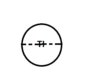
Panel mounted temperature Indicator.
p&id_representation_of_field_mounted_temperature_indicator
Temperature indicator in the DCS/PLC/Controller.
p&id_representation_of_controller_mounted_instrument
Locally mounted temperature transmitter.
p&id_representation_of_temperature_transmitter_field_mounted

Thermo element representation(Thermocouple/RTD)
p&id_representation_of_temperature_element


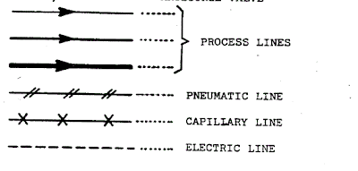
Representation of pipes and signal in P&ID:

Process lines
Pneumatic line
Capillary line
Electric line


piping_signal_represenatation

Control valves are representation in P&ID

LCV - Level control valve
PCV – Pressure control valve
TCV- Temperature control valve
FCV- Flow control valve
PSV- Pressure safety valve
ROV- Remote operated valve
MOV- Manually operated valve
FIC/V- Anti surge valve

Related post:
How to read a piping and instrument diagram?
Difference between p&id and pfd?

Minggu, 19 Juni 2011

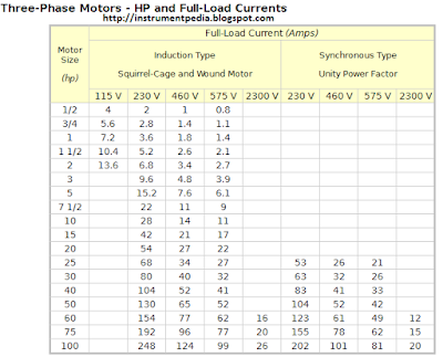
How to find out the Full load current [Relation between horse power and kilo watt] and how to select a proper cable [Power cable size selection chart]

In previous posts i have explained about electrical drawings, electrical panel component etc.. For smooth working of motor which is connected to the mcc panel, cable size selection has an important role. We have to consider lot of things for selecting a proper cable, like motor rating (Kilowatt,Horse power),Voltage(230v, 415 v etc.),Phase(Single, 3 phase),Temperature, Distance between motor and mcc.
Before that i will expalin how to find out the cable current rating.
1.Incoming suppy cable rating.
           Motor Full load current * 1.2
2.Inside cables – Motor circuit cable rating.
           Motor full load current * 0.7

Now you will be having a doubt how to find out the full load current of a motor?

Formula for finding full load current of a motor.

3 phase:
            Full load current=(746*hp)/(1.732*V*pf*eff) or KW/(1.732*v*pf*eff)
                                 hp=horse power
                                  v =Voltage
                                  pf=Power factor
                                 ef=efficiency
                              1 hp=745.7 W=0.746 kw

Single phase motor Full load current table [Horse power,Kilo watt]

full_load_current_chart_table_single_phase_motor_hp_kw

Three phase motot Full load current table [Horse power,Kilo watt]
three_phase_motor_full_load_current_calculation_horsepower_kilowatt_conversion

Cable size selection chart-Single phase
single_phase_cable_size_selection_chart_full_load_current

Cable size selection chart- Three phase

Kamis, 26 Mei 2011

What is the difference between control panel and MCC?

You know what is control panel and what are the components used in the control panel. Now we will discuss about difference between control panel and MCC. You might have faced this question in some interviews.

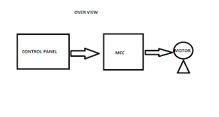
MCC stands for motor control center. It consists of feeders for motors and blowers. Feeders are designed according to the motor rating. In most of the MCCs, auto/manual provision will be there. With manual provision motors can be operated manually. In auto provision external signal is required to start the motor. The signal is given by the control panel. Indicators for the motor operation also will be present in control panel.
mcc- motor control center- control the motor by recieving signal from control panel


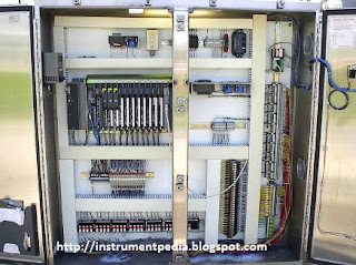
Control panel consist of a controller. Controller may be PLC, DCS, relay or some other type. It gives digital signal input signal to the MCC panel to start the motor. Control panel works based on the PLC /DCS program or the relay logic.  Instruments are normally connected to control panel. Indications for the interlocks also will be there in control panel. Nowadays single panel is used of using separate control and MCC panel.

control panel - PLC/DCS/relay recieve inputs from instrument and give outputs to MCC


Overview: Control panel giving start command to motor through MCC

How control panel control motor through MCC


Related post:
Know more about control panel.
Learn to read electrical relay drawing.
Basics of electrical.


Selasa, 24 Mei 2011

How to read electrical relay diagram? [Standard symbols used for drawing electrical relay diagram]

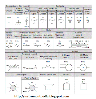
In one of the previous post in instrumentpedia I have described how to read an electrical drawing. Now lets look what is electrical relay diagram. Here I am giving the standard symbols used for the electrical relay diagram. In earlier days instead of PLC or DCS like controllers relays are used as controllers. Nowadays also for controlling small systems relays are using as controllers. Comparing to other controllers it is very cheap. Electrical control circuits are drawn with the standard symbols which are given below.

Components used for making a electrical control circuit and its standard symbols.

Switches.
Selectors.
Push buttons.
Contacts.
Coils.
Motors.
Pilot lights.
Alarms.
Connections
standard symbols electrical relay diagram- switches-pus button-connections
electrical relay diagram alarms motor hooter contacts

Related post:
Learn to read an electrical drawing.
Basics of electrical engineering
Electrical control panels
Piping and instrument diagram