Tampilkan postingan dengan label Electrical. Tampilkan semua postingan

Sabtu, 24 Desember 2011

Ingression protection

While reading the instrument specification or electrical equipment specification you might have seen IP classes.IP is interpreted as Ingress protection.Ip calsses stands for specifying the environmental protection of electrical equipments. With ingression protection class we can understand, an instrument can withstand in which environmental condition. While selecting the instrument it is important to consider the ip class. Price of the instrument also varies according to their ip class.

IP class is represented with number. First digit of IP indicates how much the instrument is protected from dust. Second digit of the IP rating indicates how much the instrument is protected from water.

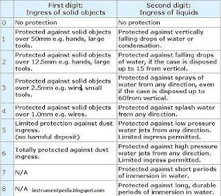
First digit of IP rating
0 = No protection
1 = Protected against touch by hands (>50mm)
2 = Protected against touch by fingers (>12mm)
3 = Protected against tools and wires (>2.5mm)
4 = Protected against tools and small wires (>1mm)
5 = Limited dust ingress protection
6 = Total dust ingress protection

Second digit of IP rating
0 = No protection
1 = Protected against condensation
2 = Protected against water spray < 15 degrees from vertical
3 = Protected against water spray < 60 degrees from vertical
4 = Protected against water spray from any direction
5 = Protected against low pressure water jets from any direction
6 = Protected against high pressure water jets from any direction
7 = Protected against immersion between 15cm and 1m depth
8 = Protected against long term immersion to a specified pressure

IP rating of electrical equipment or instrument


Minggu, 19 Juni 2011

How to find out the Full load current [Relation between horse power and kilo watt] and how to select a proper cable [Power cable size selection chart]

In previous posts i have explained about electrical drawings, electrical panel component etc.. For smooth working of motor which is connected to the mcc panel, cable size selection has an important role. We have to consider lot of things for selecting a proper cable, like motor rating (Kilowatt,Horse power),Voltage(230v, 415 v etc.),Phase(Single, 3 phase),Temperature, Distance between motor and mcc.
Before that i will expalin how to find out the cable current rating.
1.Incoming suppy cable rating.
           Motor Full load current * 1.2
2.Inside cables – Motor circuit cable rating.
           Motor full load current * 0.7

Now you will be having a doubt how to find out the full load current of a motor?

Formula for finding full load current of a motor.

3 phase:
            Full load current=(746*hp)/(1.732*V*pf*eff) or KW/(1.732*v*pf*eff)
                                 hp=horse power
                                  v =Voltage
                                  pf=Power factor
                                 ef=efficiency
                              1 hp=745.7 W=0.746 kw

Single phase motor Full load current table [Horse power,Kilo watt]

full_load_current_chart_table_single_phase_motor_hp_kw

Three phase motot Full load current table [Horse power,Kilo watt]
three_phase_motor_full_load_current_calculation_horsepower_kilowatt_conversion

Cable size selection chart-Single phase
single_phase_cable_size_selection_chart_full_load_current

Cable size selection chart- Three phase

Kamis, 26 Mei 2011

What is the difference between control panel and MCC?

You know what is control panel and what are the components used in the control panel. Now we will discuss about difference between control panel and MCC. You might have faced this question in some interviews.

MCC stands for motor control center. It consists of feeders for motors and blowers. Feeders are designed according to the motor rating. In most of the MCCs, auto/manual provision will be there. With manual provision motors can be operated manually. In auto provision external signal is required to start the motor. The signal is given by the control panel. Indicators for the motor operation also will be present in control panel.
mcc- motor control center- control the motor by recieving signal from control panel


Control panel consist of a controller. Controller may be PLC, DCS, relay or some other type. It gives digital signal input signal to the MCC panel to start the motor. Control panel works based on the PLC /DCS program or the relay logic.  Instruments are normally connected to control panel. Indications for the interlocks also will be there in control panel. Nowadays single panel is used of using separate control and MCC panel.

control panel - PLC/DCS/relay recieve inputs from instrument and give outputs to MCC


Overview: Control panel giving start command to motor through MCC

How control panel control motor through MCC


Related post:
Know more about control panel.
Learn to read electrical relay drawing.
Basics of electrical.


Selasa, 24 Mei 2011

How to read electrical relay diagram? [Standard symbols used for drawing electrical relay diagram]

In one of the previous post in instrumentpedia I have described how to read an electrical drawing. Now lets look what is electrical relay diagram. Here I am giving the standard symbols used for the electrical relay diagram. In earlier days instead of PLC or DCS like controllers relays are used as controllers. Nowadays also for controlling small systems relays are using as controllers. Comparing to other controllers it is very cheap. Electrical control circuits are drawn with the standard symbols which are given below.

Components used for making a electrical control circuit and its standard symbols.

Switches.
Selectors.
Push buttons.
Contacts.
Coils.
Motors.
Pilot lights.
Alarms.
Connections
standard symbols electrical relay diagram- switches-pus button-connections
electrical relay diagram alarms motor hooter contacts

Related post:
Learn to read an electrical drawing.
Basics of electrical engineering
Electrical control panels
Piping and instrument diagram


Minggu, 03 April 2011

Meters used in the MCC panel.

Different types of meters are used in the MCC panel for indicating the status of the panel.Mainly three types of meters are used. Ammeter, Volt meter, Watt meter, Energy meter. Analog and Digital type meters are using nowadays.

Ammeter

Instrument used for measuring the current flow in the circuit is called ammeter. It should be connected series to the circuit .

Analog ammeter
analog ammeter-measuring the current flow

Digital ammeter
digital ammeter

Voltmeter

Instrument used for measuring the voltage across in the circuit is called voltmeter. It should be connected paralled to the circuit.

Analog volt meter
analog voltmeter- measuring the voltage across the circuit

Digital volt meter

digital volt meter


Wattmeter


watt meter

Energy meter

This is also called as a watt-hour meter. Energy meter is used for  measurinh the energy consumed in a circuit.

Analog Energy meter

energy meter

Digital Energy meter.


measures the energy consumption

Related post:
The wattmeter is an instrument for measuring the electric power (or the supply rate of electrical energy) in watts of any given circuit.